
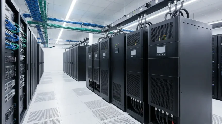
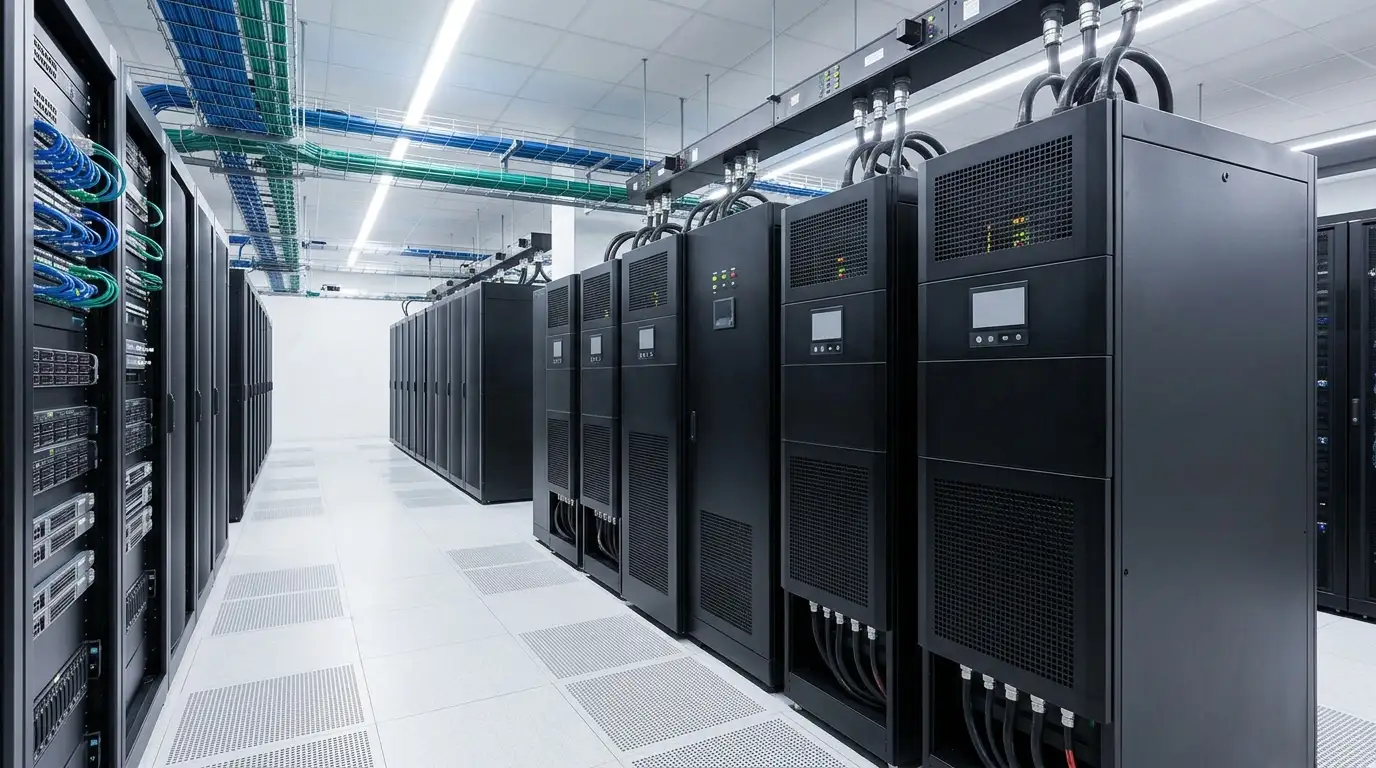
A power interruption lasting only seconds can disrupt critical workloads, damage equipment, and compromise data center operations. Uninterruptible power systems provide the immediate protection needed to maintain continuous IT availability.
From UPS systems and batteries to redundancy, sizing, and monitoring, every element influences power resilience. Understanding these systems helps data center operators maintain reliable performance while preparing for failures and future capacity demands.
Key Takeaways:
- A data center UPS provides immediate power continuity and protects critical IT equipment during utility interruptions.
- UPS systems combine batteries, power conversion, bypass circuits, and monitoring to maintain reliable power delivery.
- N+1, 2N, and 2N+1 redundancy architectures improve fault tolerance and support maintenance without interrupting critical operations.
- Required battery runtime depends on load, battery condition, generator startup, and the overall backup power strategy.
- Proper UPS sizing balances current IT load, power factor, redundancy, future growth, and scalability.
What Is Data Center Uninterruptible Power?
Data center uninterruptible power refers to electrical systems designed to maintain continuous power availability for critical IT equipment when the normal utility supply becomes unstable or unavailable.
Uninterruptible power supply (UPS) systems provide immediate protection against power interruptions, helping maintain continuous operations while backup generation becomes available. This makes UPS infrastructure essential for critical computing environments.
Unlike conventional backup power, which may require time to start, UPS systems respond immediately and can provide temporary power during outages. They also help protect equipment against electrical disturbances and unstable supply conditions.
Read Also: Data Center Electrical Infrastructure, Boost Uptime Now!
How Does a Data Center UPS System Work?
A data center UPS system operates as part of a coordinated power architecture, managing electricity between the utility source, energy storage, backup generation, and critical IT loads.
1. Normal Power Operation
During normal operation, utility electricity supplies the facility while the UPS continuously manages power delivery to connected equipment. Its operation helps maintain stable electrical conditions for sensitive computing loads.
The UPS can provide power conditioning while supplying electricity to IT equipment. Depending on its configuration, the system manages voltage and other electrical characteristics before power reaches connected loads.
2. Power Failure Operation
When the utility supply fails or becomes unavailable, the UPS detects the interruption and immediately transfers the critical load to its stored energy source, maintaining continuous power delivery.
The UPS battery provides immediate support while standby generators start and stabilize. This transition allows generators to assume longer-duration backup duties without requiring critical IT equipment to experience an interruption.
3. Power Restoration
Once utility power returns, the electrical system must transition back from generator-supported operation while maintaining stable power delivery to critical loads throughout the recovery process.
After utility power is restored and conditions stabilize, the UPS resumes normal operation and recharges its batteries. Proper synchronization and recovery procedures help prepare the system for future interruptions.
Key Components of a Data Center Uninterruptible Power System
A data center UPS system combines power conversion, energy storage, switching, and monitoring components to maintain continuous power for critical loads during normal operation and electrical disturbances.
1. UPS Modules
UPS modules contain the primary power-conversion equipment responsible for delivering protected electricity to critical loads. Data centers can use centralized systems or modular architectures depending on capacity, redundancy, and expansion requirements.
A centralized UPS generally operates as a larger integrated system, while modular UPS architectures use independent power modules that can support incremental capacity additions and redundancy as demand changes.
Single-module configurations can provide straightforward power protection, while multi-module systems can support N+1 redundancy, maintenance flexibility, and capacity expansion without necessarily replacing the entire UPS installation.
2. UPS Batteries
UPS batteries store electrical energy that can immediately support critical loads when the normal power source becomes unavailable. Battery capacity directly influences the available UPS runtime during an interruption.
Common technologies include valve-regulated lead-acid (VRLA) and lithium-ion batteries. Selection depends on runtime requirements, footprint, operating conditions, maintenance strategy, lifecycle considerations, and overall data center design objectives.
3. Rectifier and Inverter
The rectifier converts incoming AC power into DC power for the UPS’s internal DC link, while the inverter converts DC power back into controlled AC power for connected critical loads.
In a double-conversion UPS, these conversion stages continuously process power before delivery to IT equipment. This architecture enables voltage and frequency regulation while providing continuous protection from many upstream electrical disturbances.
4. Static Bypass
A static bypass provides an alternative electrical path that can transfer critical loads away from the UPS power-conversion path under specific fault, overload, or maintenance conditions.
Bypass operation can support maintenance and fault management, but its architecture must be carefully designed around availability requirements, fault-clearing capability, and protection coordination to avoid creating additional failure dependencies.
5. UPS Monitoring and Control Systems
UPS monitoring and control systems provide visibility into operating conditions, battery status, alarms, load levels, and other parameters needed to manage critical power infrastructure effectively.
Continuous monitoring can identify abnormal conditions before they develop into operational problems. Remote management also helps operators track UPS performance, coordinate maintenance, and respond quickly to equipment alarms or changing loads.
Types of UPS Systems Used in Data Centers
Different UPS topologies provide different levels of power conditioning, efficiency, and protection. Selecting an appropriate configuration requires considering the sensitivity of connected equipment, availability requirements, capacity, redundancy, and expected operating conditions.
1. Standby UPS
A standby UPS, also called a voltage-and-frequency-dependent system, normally allows utility power to supply the connected load while providing battery-backed protection when the input source fails.
This topology provides basic power protection and can suit less demanding applications. However, critical data center environments generally require more comprehensive power conditioning and continuous protection than basic standby configurations provide.
2. Line-Interactive UPS
A line-interactive UPS provides greater power conditioning than standby designs while remaining more efficient in certain operating conditions. It can regulate voltage variations without relying exclusively on battery operation.
This topology can be appropriate where moderate power conditioning is sufficient. However, data center applications with highly critical loads may require higher protection levels, particularly where voltage and frequency disturbances present significant operational risks.
3. Online Double-Conversion UPS
An online double-conversion UPS continuously converts incoming AC power to DC and then back to regulated AC power before supplying connected critical loads.
This architecture provides a high level of power conditioning and enables no-break protection during source disturbances. It is widely associated with critical data center environments requiring stable, continuously protected power for sensitive IT equipment.
Data Center UPS Redundancy
Data center UPS redundancy determines how much backup capacity remains available when individual UPS modules fail or require maintenance. Common architectures include N+1, 2N, and 2N+1 configurations.
1. N+1 UPS Redundancy
N+1 UPS redundancy provides one additional UPS module beyond the number required to support the critical load. If one module fails, remaining capacity can continue supporting connected IT equipment.
This architecture can also support maintenance activities without interrupting operations, provided sufficient capacity remains available after removing a module from service. It balances resilience, capacity, and infrastructure requirements.
2. 2N UPS Redundancy
2N UPS redundancy uses two independent UPS systems, with each system capable of supporting the complete critical load. This architecture creates separate power paths and reduces dependency on individual equipment.
Because either UPS system can theoretically support the full load independently, 2N architecture can provide greater fault isolation and maintenance flexibility for highly critical data center environments.
3. 2N+1 UPS Redundancy
2N+1 UPS redundancy combines two independent complete power systems with an additional redundant capacity element. This architecture provides additional tolerance against equipment failures beyond conventional dual-system configurations.
The architecture can support maintenance and component failures while maintaining required capacity. Its effectiveness depends on appropriate distribution, switching, protection, and operational procedures across the entire electrical infrastructure.
4. Redundancy, Fault Tolerance, and Availability
UPS redundancy improves fault tolerance by reducing dependence on individual components or power paths. However, redundancy alone does not guarantee availability because distribution, controls, maintenance, and operational procedures also influence system resilience.
Higher redundancy can support maintenance without downtime when the remaining infrastructure retains sufficient capacity and follows appropriate operating procedures. Therefore, redundancy should align with availability objectives rather than capacity requirements alone.
Data Center UPS Battery Runtime
UPS battery runtime describes how long a UPS can continue supplying connected critical loads from stored electrical energy after normal utility power becomes unavailable.
1. What UPS Runtime Means
UPS runtime represents the period during which stored battery energy can support the connected critical load following a power interruption. Runtime depends on battery capacity, load demand, battery condition, and operating conditions.
Longer runtime provides additional time for operators or automated systems to respond to an outage. However, the required duration should reflect the overall backup-power strategy and operational objectives.
2. Factors Affecting Battery Runtime
Several factors influence UPS battery runtime, including connected load, battery capacity, battery age, temperature, discharge characteristics, and charging conditions. Higher electrical loads generally reduce the available runtime.
Battery technology and system efficiency also affect runtime characteristics. Regular monitoring helps operators understand battery health and identify degradation that could reduce expected backup performance.
3. UPS Runtime and Generator Startup
In generator-backed data centers, UPS batteries typically bridge the interval between utility failure and generator availability. The required runtime therefore depends partly on generator startup, stabilization, and transfer processes.
The UPS must maintain stable power throughout this transition without exposing critical IT equipment to interruption. Adequate runtime provides operational margin when generator startup or transfer takes longer than expected.
4. Why Longer Runtime Is Not Always Necessary
Increasing battery runtime can require additional battery capacity, physical space, cooling, maintenance, and capital investment. Consequently, maximizing runtime does not necessarily provide proportional improvements in overall data center resilience.
A well-designed system should coordinate UPS runtime, generator capability, load requirements, and operational procedures. The objective is sufficient ride-through capability rather than unnecessarily maximizing stored energy.
Data Center UPS Capacity and Sizing
Data center UPS capacity and sizing determine whether the electrical system can reliably support current loads while maintaining appropriate redundancy and allowing future IT capacity growth.
1. Calculating IT Load
UPS sizing begins with accurately determining the connected IT load, including servers, storage systems, networking equipment, and other critical electrical loads requiring uninterrupted power.
Operators should consider actual operating demand rather than relying solely on equipment nameplate ratings. Accurate load measurements provide a stronger foundation for determining required UPS capacity and redundancy.
2. UPS Capacity and Power Factor
UPS capacity is commonly expressed using kilovolt-amperes (kVA) and kilowatts (kW). The relationship between these measurements depends on the UPS and connected equipment’s power factor.
Understanding power factor helps operators avoid selecting equipment based solely on apparent power. The UPS should provide sufficient kW and kVA capacity for the expected electrical characteristics of connected loads.
3. Future Capacity Requirements
UPS sizing should consider expected future IT deployments, including additional servers, storage, networking infrastructure, and higher-density computing environments. Planning only for current demand can constrain future expansion.
Capacity planning should establish realistic growth assumptions while considering available electrical infrastructure, physical space, cooling requirements, and redundancy objectives. This approach helps prevent premature infrastructure replacement.
4. Load Growth and Scalability
Load growth can increase UPS utilization over time, making scalability an important consideration when selecting centralized or modular architectures. Modular systems can provide additional capacity as electrical demand increases.
Avoiding UPS undersizing prevents excessive loading and capacity constraints, while avoiding excessive oversizing can reduce utilization and increase unnecessary capital expenditure. Effective planning balances present requirements with future scalability.
For future deployments, operators should evaluate expected IT growth, rack density, redundancy requirements, available electrical capacity, and expansion timelines. This creates a scalable UPS architecture capable of supporting changing workloads without disruptive redesign.
References:
- U.S. Department of Energy. Best Practices Guide for Energy-Efficient Data Center Design. DOE — Best Practices Guide for Energy-Efficient Data Center Design.
- U.S. Department of Energy. Purchasing Energy-Efficient Uninterruptible Power Supplies. DOE — Purchasing Energy-Efficient UPSs.
- U.S. Department of Energy / Pacific Northwest National Laboratory. Data Center EMT Models. DOE/PNNL — Data Center EMT Models.
- Vertiv. Enhancing UPS Reliability. Vertiv — Enhancing UPS Reliability.