
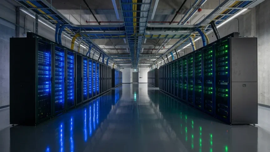
Modern digital enterprises rely on robust infrastructure to power continuous online operations and heavy computational workloads. Designing these complex facilities requires a strategic balance between high availability, energy efficiency, and operational safety.
A well-executed data center design serves as the foundation for enterprise scalability, seamless connectivity, and long-term business continuity. Engineers must align physical space, power distribution, and thermal management to support evolving hardware demands.
What is Data Center Design?
Modern data center design is an integrated engineering discipline combining structural, electrical, thermal, and networking systems. It transforms raw physical space into a highly secure environment engineered specifically for continuous computational processing.
By unifying hardware needs with facility logistics, proper data center design prevents costly operational bottlenecks. It ensures that critical hardware operates within safe environmental thresholds at all times.
The Core Objectives: Uptime, Efficiency, and Safety
Achieving maximum system availability requires balancing continuous operational uptime with aggressive power usage effectiveness targets. Facility managers must minimize energy waste while maintaining strict fault tolerance across all operational layers.
Safety protocols protect sensitive equipment from environmental threats, fire hazards, and electrical anomalies. Aligning these three pillars creates an optimal ecosystem for critical IT assets within any data center design.
Read Also: Power Line Conditioner: Is One Really Necessary for Gear?
Key Parameters for Modern Facilities
Key engineering metrics define performance standards for modern IT environments:
- Power Density: Rack power density ranges from 10 kW to over 100 kW per cabinet.
- Floor Load: High-density server deployments require reinforced slab floor loading capacities.
- Network Latency: Internal network topologies are optimized for sub-millisecond packet delay.
- Future Growth: Flexible floor plans accommodate dynamic spatial and power expansion needs.
Strategic Site Selection and Physical Architecture
Choosing the right physical location forms the groundwork for facility resilience and operational longevity. Engineers evaluate external environmental risks, utility access, and structural layouts before construction begins.
1. Environmental and Risk Assessment
Site selection begins with analyzing geological stability to avoid active fault lines and severe seismic hazard zones. Facilities are positioned outside 100-year floodplains to mitigate water-related risks during extreme weather events.
Planners also consider local ambient temperatures to leverage free-air cooling opportunities during colder months. Safe physical distances from chemical plants or high-risk industrial hazards protect structural integrity and personnel safety.
2. Utility Accessibility and Fiber Connectivity
Proximity to robust electrical utility grids is vital for establishing high-capacity substation connections. Facilities require dual-feed power architecture originating from distinct utility substations to guarantee uninterrupted energy delivery.
Redundant carrier-neutral fiber pathways enter the facility through physically separated entry vaults into dedicated meet-me rooms.
3. Modular White-Space Floor Planning
Efficient facility layouts divide usable area into IT-dedicated white space and mechanical gray space. This operational separation ensures maintenance teams can service heavy equipment without entering sensitive server halls.
A modular data center design allows operators to deploy additional computing pods incrementally as capacity demands grow. This structured approach optimizes capital expenditure while maintaining clean airflow dynamics.
Core Infrastructure Systems: Power Distribution and Resiliency
A robust electrical architecture delivers continuous, clean power from external utility sources directly to sensitive IT equipment. Redundant power paths protect operations against severe grid fluctuations and total blackouts.
1. High-Voltage Utility Grid Inputs and Transformers
Facilities connect directly to regional high-voltage utility grids to secure massive power allocations for server equipment. On-site step-down transformers convert incoming utility voltages into usable, lower-voltage electricity for internal distribution infrastructure.
Dual-substation feed designs ensure uninterrupted energy transfer if one utility grid source suffers an outage. This primary electrical isolation guards internal hardware against hazardous utility grid voltage spikes.
2. Uninterruptible Power Supply (UPS) Systems
Uninterruptible power supply units act as the immediate bridge between utility outages and backup generator initialization. Modern facilities increasingly deploy lithium-ion batteries due to their higher energy density, smaller footprint, and longer operational lifespan.
Alternative solutions like kinetic flywheel systems deliver short bursts of clean power with minimal maintenance overhead. These systems smooth out power fluctuations and prevent server reboots during voltage sags.
3. Emergency Backup Generators and Fuel Storage
When primary grid power fails completely, industrial diesel or natural gas generators assume the full electrical load. Fast-acting automatic transfer switches detect voltage loss and start backup engines within seconds to maintain uninterrupted operational continuity.
On-site fuel storage tanks are sized to sustain full-facility operations for 24 to 72 hours continuously. Regular load-bank testing ensures these emergency systems respond reliably during actual power disasters.
4. Power Distribution Units and Smart Racks
Floor-mounted power distribution units step down voltage and supply clean electrical feeds to individual server rows. Deploying intelligent rack PDUs enables precise outlet-level power metering, remote switching, and active load monitoring.
Furthermore, maintaining active phase balancing prevents neutral conductor overloading across three-phase power circuits. This integrated electrical management guarantees reliable energy distribution at the rack level.
Advanced Cooling and Thermal Management Systems
High-performance computing chips generate immense heat loads that must be continuously removed to prevent equipment failure. Modern thermal management combines intelligent airflow management with direct liquid cooling solutions.
1. Airflow Optimization: Hot and Cold Aisle Containment
Preventing cold supply air from mixing with hot server exhaust forms the basis of efficient thermal management. Installing hot aisle containment or cold aisle containment physical barriers dramatically increases cooling system efficiency and lowers operating costs.
Utilizing raised floors or direct slab overhead ducting guides conditioned air precisely where hardware requires it. Eliminating thermal recirculation allows facilities to safely increase baseline room temperatures.
2. High-Density Liquid Cooling Systems
Legacy air cooling systems struggle to dissipate thermal output from modern GPU clusters exceeding 40 kW per rack. Advanced direct-to-chip cooling circulates dielectric fluid or treated water directly across processor cold plates to extract heat instantly.
For extreme computational densities, full immersion cooling submerges entire server blades into non-conductive liquid baths. These liquid methodologies deliver superior heat transfer efficiency required for modern AI infrastructure.
3. Economizers and Free Cooling Mechanisms
Deploying air-side economizers draws cool external air directly into the facility, reducing reliance on mechanical chillers. Alternatively, water-side economizers utilize evaporative cooling towers to chill loop water efficiently during favorable weather conditions.
Integrating these free cooling methods leads to significant PUE reduction by lowering overall HVAC energy consumption. Facilities dramatically improve seasonal operational efficiency while reducing mechanical wear.
Redundancy Tiers and Fault-Tolerant Architectures
Standardized classification systems help operators quantify facility reliability, operational availability, and structural resilience. Redundant engineering design eliminates single points of failure across all critical mechanical and electrical subsystems.
1. Demystifying Redundancy Formulas (N+1, 2N, 2N+1)
Baseline system capacity is represented as $N$, satisfying basic operational requirements without extra reserve capacity. An $N+1$ configuration adds one extra component, providing active parallel redundancy during routine maintenance or equipment failures.
A fully isolated $2N$ architecture mirrors the entire power distribution path, creating complete dual-path system redundancy. Multi-bus redundancy ($2N+1$) offers maximum protection, ensuring zero interruption during simultaneous system failures.
2. Understanding Availability Standards (Uptime Institute Tiers I–IV)
The Uptime Institute categorizes facilities into four distinct tier levels based on availability and fault tolerance. Tier I facilities provide basic capacity without redundant components, whereas Tier II adds partial system redundancy.
Tier III facilities enable concurrent maintainability, allowing equipment servicing without interrupting active server workloads. Tier IV achieves full fault tolerance, offering 99.999% uptime through compartmentalized, dual-powered infrastructure components.
Layout Planning and Physical Network Architecture
Optimized floor layouts and structured cabling systems drive low latency and high bandwidth performance. Modern networking architectures accelerate internal server communications while ensuring seamless external carrier connectivity.
1. Physical Topology and Cable Management
Implementing standardized structured cabling maintains clean connectivity and simplifies network maintenance across all server aisles. Overhead cable trays keep physical pathways accessible while preventing under-floor airflow blockages that cause localized hotspots.
Proper spatial planning optimizes rack placement density to balance equipment weight and electrical loads evenly. This structured physical arrangement supports continuous airflow and efficient hardware management.
2. Modern Network Fabrics: Spine-and-Leaf Architecture
Traditional three-tier network architectures often create bandwidth bottlenecks and elevated latency during heavy internal data transfers. Replacing them with two-tier spine-and-leaf topology ensures predictable, ultra-low latency connection paths between all deployed servers.
Every leaf switch connects directly to every spine switch, optimizing high-volume east-west traffic flows. This flat network structure scales seamlessly as extra rack rows are added to the facility.
Facility Management, Monitoring, and Automation Tools
Integrated software platforms provide facility managers with comprehensive visibility into operational performance, power draw, and environmental conditions. Continuous automated monitoring prevents equipment failures and optimizes resource utilization.
1. Building Management Systems (BMS)
A central building management system supervises heavy mechanical infrastructure, including chillers, air handlers, and primary electrical distribution units. It continuously collects sensor data to adjust environmental parameters automatically based on changing room conditions.
Integrated fire suppression systems rely on BMS telemetry to detect early smoke signatures and deploy localized gas suppression safely. Automated monitoring protects both physical assets and personnel without human intervention.
2. Data Center Infrastructure Management (DCIM)
DCIM software bridges the gap between traditional facility management and active IT hardware monitoring within server racks. It tracks operational metrics including power consumption, dynamic thermal distribution, and real-time floor space availability across all white spaces.
Advanced predictive capabilities allow operators to run thermal simulations and model future capacity constraints accurately. Using intelligent insights prevents unexpected circuit overloads and optimizes long-term facility usage.
3. Physical Security and Multi-Layer Access Controls
Robust perimeter protection combines physical fencing, vehicle barriers, and intrusion detection systems to prevent unauthorized access. Inside the building, biometric access controls and continuous video surveillance restrict entry to secure server halls.
Furthermore, high-density environments utilize compartmentalized cages to isolate sensitive hardware within dedicated enclosures. This layered approach ensures complete physical safety for critical enterprise data assets.