

In today’s digital age, facilities must maintain non-stop operations to support critical workloads. Any unexpected electrical disruption can compromise server integrity and cause severe operational failure.
Implementing a robust uninterruptible power supply is the ultimate line of defense for modern infrastructure. This guide explores how these advanced systems secure continuous operations and optimize overall energy efficiency.
What is a Data Center UPS System?

Technician managing server racks in a modern data center, ensuring optimal performance and network efficiency.
A data center UPS system is a critical electrical device that supplies emergency backup power in the event of a failure in the primary utility power source. It serves as the resilient backbone of IT infrastructure by safeguarding sensitive hardware from unexpected grid instability.
Without this vital protection, facilities face catastrophic data corruption and expensive hardware degradation. Maintaining clean, continuous electricity is paramount to preventing operational downtime and keeping digital services online around the clock.
Key Functions of a UPS System in Data Centers
Modern backup power frameworks do more than just store emergency energy for hardware. They act as comprehensive power-conditioning systems that safeguard entire enterprise networks from various utility grid anomalies.
1. Seamless Power Transition
If the primary utility grid fails unexpectedly, the uninterruptible power supply engages without a millisecond of delay. It bridges the critical operational gap before backup diesel generators can ramp up and accept the full load.
This immediate response relies on stored energy to ensure that critical network servers experience no electrical interruption. The seamless handoff prevents system reboots, protecting active user sessions and ongoing cloud database transactions.
Read Also: What is a 3 Phase UPS? Working Principles & Benefits
2. Equipment Protection and Voltage Stabilization
Utility lines are frequently plagued by hazardous anomalies like voltage sags, spikes, and transient line noise. A dedicated data center ups system constantly conditions incoming power to deliver a smooth, stable output.
By absorbing harmful spikes and boosting low voltages, it shields sensitive computing components from premature wear. This continuous regulation extends the operational lifespan of expensive enterprise storage systems and high-density blade servers.
3. Ensuring Business Continuity
Unplanned downtime translates directly to massive financial losses, ruined consumer trust, and breached service level agreements. A robust emergency power architecture ensures your digital applications remain completely accessible during severe grid failures.
By shielding critical infrastructure, businesses can maintain continuous operations without facing expensive service halts. This system guarantees operational peace of mind, proving that reliable power is critical for modern commercial success.
How Does a Data Center UPS Work?
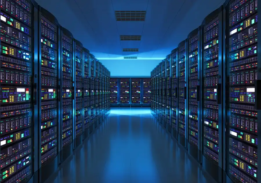
Data Center UPS Systems
Understanding the inner workings of emergency power systems helps operators optimize their overall facility management. These systems smoothly shift between distinct operational modes depending on the current state of the main utility line.
1. Normal Operating Conditions
During standard grid operations, the system receives raw alternating current directly from the utility provider. An internal rectifier seamlessly changes this electricity into direct current to charge the energy storage bank.
Simultaneously, the internal inverter path converts that cleaned power back into stable alternating current. This continuous double-conversion process ensures that the connected IT load receives purified, high-quality electricity.
2. Power Outage and Disturbance Scenarios
The moment the main electrical supply fails or drops below safe thresholds, the system changes behavior. The internal storage bank instantly discharges its power directly to the inverter without a single millisecond of delay.
This critical zero transfer time ensures that critical computing processes remain entirely uninterrupted. Connected network equipment continues to run smoothly, completely isolated from the external utility grid failure.
Core Components of a Data Center UPS Architecture
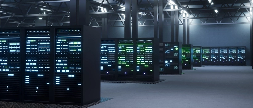
Data Center UPS Systems
An enterprise-grade emergency power setup consists of several highly specialized internal components working together. Each integrated part is crucial for maintaining system reliability and delivering clean power to the facility.
1. Rectifier (Charger)
The internal rectifier serves as the vital entry gate for incoming utility electricity. Its primary technical job is to convert incoming AC power into a stable DC format.
This generated DC electricity fulfills two essential operational roles inside the emergency power architecture. It continuously feeds the energy storage bank while simultaneously sending clean power to the system’s inverter.
Read Also: What Is a Modular UPS? Its Benefits and How It Works
2. Battery Bank
The battery bank represents the heart of the backup system, acting as the primary energy reservoir. It dictates the total runtime available to sustain the critical IT load during a blackout.
Because these energy cells are susceptible to chemical degradation, they demand strict routine maintenance. Consistent testing ensures maximum reliability, preventing unexpected cell failures when emergency power is needed most.
3. Inverter
The internal inverter acts as the final conditioning stage before power reaches critical IT equipment. It takes the DC power from the rectifier or batteries and converts it back to AC.
This process creates a pristine, regulated sine wave output that eliminates harmful voltage fluctuations. It guarantees that sensitive server power supplies receive clean, stable electricity regardless of incoming grid conditions.
4. Static Bypass Switch
The static bypass switch is a critical safety mechanism that protects the facility from internal system failures. If the internal circuitry overheats or suffers a fault, this switch activates instantly.
It safely reroutes the electrical path directly from the utility line to the server racks. This ensures connected IT hardware remains energized and online even during an internal component emergency.
5. Centralized Monitoring System
A modern monitoring system provides critical real-time visibility into the health of the entire power architecture. It constantly tracks vital metrics like cell temperature, load percentages, and total remaining runtime.
By utilizing advanced power management software, facility managers receive instant alerts regarding potential system anomalies. This proactive insight enables swift maintenance before minor component issues escalate into costly operational failures.
Understanding UPS Topologies: Which is Best for Data Centers?
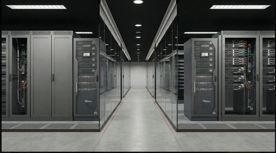
Data Center UPS Systems
Not all backup architectures offer the same level of protection and electrical isolation. Selecting the right topology depends on your specific facility scale, budget limitations, and uptime requirements.
1. Off-Line / Standby UPS
An off-line ups keeps its internal inverter idling until a utility power failure is detected. When grid electricity drops, a mechanical switch transfers the critical IT load over to the battery source.
This mechanical transfer introduces a brief transfer time delay of several milliseconds. While acceptable for basic desktop computers, this interruption makes it unsuitable for mission-critical core infrastructure.
Read Also: Static Transfer Switch: Components, How It Works & Benefits
2. Line-Interactive UPS
A line-interactive topology features a specialized variable transformer that actively regulates incoming voltage fluctuations. It can handle minor sags and surges without draining the primary emergency battery bank.
This approach offers improved efficiency and better power conditioning than basic standby models. However, it still exhibits a small transfer delay, making it ideal mainly for edge network closets.
3. Online Double-Conversion UPS
An online double-conversion system provides absolute isolation by continuously converting power from AC to DC, then back to AC. This design ensures that raw utility fluctuations never reach the sensitive IT hardware directly.
Because the inverter is always actively feeding the load, there is absolutely zero transfer delay during blackouts. This premium topology is the mandatory industry standard for mission-critical enterprise hubs and colocation data centers.
UPS Redundancy Configurations for Data Center Design
Engineering a resilient power layout requires balancing initial capital costs against required availability targets. System designers use specific redundancy configurations to eliminate single points of failure within the facility.
1. N Configuration (Base Capacity)
The N configuration represents the exact baseline power capacity required to run the facility at full load. This straightforward design contains no extra backup modules or secondary electrical safety nets.
If a single power module requires maintenance or breaks down, the connected IT load will fail. It represents a cost-effective choice but leaves the facility highly vulnerable to unexpected operational downtime.
Read Also: Rack Mount UPS: Types, Functions, and Tips for Choosing
2. N+1 Configuration (Module Redundancy)
An N+1 redundancy strategy introduces at least one extra power module into the active parallel system. If any single module fails, the remaining units absorb the electrical load without interrupting operations.
This approach offers an affordable way to increase facility resilience during unexpected hardware issues. It allows technicians to perform routine repairs on individual units without taking the entire server room offline.
3. 2N Configuration (System Plus System)
The 2N redundancy model creates a fully duplicated power infrastructure featuring two completely independent electrical distribution pathways. Each independent path is capable of running the entire facility’s maximum load by itself.
Even if an entire power line suffers a catastrophic failure, the secondary pathway maintains smooth operations. While this configuration demands a high initial investment, it offers maximum protection for Tier IV facilities.
Major Challenges and Considerations in Designing a Data Center UPS System
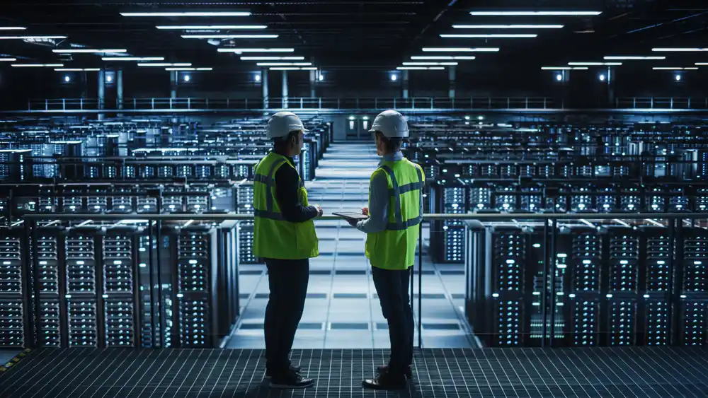
Data Center UPS Systems
Creating a dependable backup power infrastructure involves navigating complex architectural and environmental constraints. Engineers must evaluate several physical variables to ensure long-term efficiency and system scalability.
1. Thermal Management and Cooling Requirements
Emergency valve-regulated lead-acid batteries are highly sensitive to elevated ambient temperatures. Excess environmental heat accelerates internal chemical degradation, significantly shortening the overall working life of your cells.
Consequently, dedicated backup power rooms require robust cooling infrastructure to maintain optimal climate conditions. Proper ventilation prevents dangerous thermal runaway, ensuring the energy storage system performs reliably when needed.
2, Load Capacity and Future Scalability (kVA vs. kW)
Designers must understand the critical difference between apparent power measured in kVA and actual real power in kW. Modern computing systems operate at a near-unity power factor, demanding precise electrical alignment.
Furthermore, the overall power design must incorporate flexible scalability to support growing computational demands. Selecting a modular architecture allows operators to expand backup capacity seamlessly as their server hardware grows.
3. Physical Footprint and Space Optimization
Heavy battery cabinets and massive power modules occupy valuable square footage inside an industrial facility. Optimizing the physical footprint is essential to maximize the space available for revenue-generating server racks.